Saturday, October 21, 2017

Digest of ESPRIT Algorithm

For most folks, ESPRIT means a fashion branch (http://www.esprit.eu/). But for nerds, ESPRIT stands for Estimation of Signal Parameter via Rotational Invariance Technique. It is a signal processing algorithm used to process things like signal coming from array. ESPRIT is often mentioned together with MUSIC algorithm. Again, MUSIC is not the real music played by Mozart but stands for MUltiple SIgnal Classification.

Recently I spent some time to understand the details of ESPRIT algorithm and here is what I have learnt. The biggest difference between ESPRIT and MUSIC is that ESPRIT has dual receivers. The diagram below is from a tutorial found in Internet (http://www.girdsystems.com/pdf/GIRD_Systems_Intro_to_MUSIC_ESPRIT.pdf). As shown here, to make ESPRIT algorithm possible, there are many pairs of sensors. The angle of arrive signal is obtained by comparing these two received signals.


The best way for understanding such algorithm is to run a Matlab script. The website of a book named "Spectral Analysis of Signals" provide a well written example of Matlab code for ESPRIT. The code is as below:


function w=esprit(y,n,m)
%
% The ESPRIT method for frequency estimation.
%
%  w=esprit(y,n,m);
%
%      y  ->  the data vector
%      n  ->  the model order
%      m  ->  the order of the covariance matrix in (4.5.14)
%      w  <-  the frequency estimates
%

% Copyright 1996 by R. Moses

y=y(:);
N=length(y);                       % data length

% compute the sample covariance matrix
R=zeros(m,m);
for i = m : N,
   R=R+y(i:-1:i-m+1)*y(i:-1:i-m+1)'/N;
end

% to use the forward-backward approach, uncomment the next line
% R=(R+fliplr(eye(m))*R.'*fliplr(eye(m)))/2;

% get the eigendecomposition of R; use svd because it sorts eigenvalues
[U,D,V]=svd(R);
S=U(:,1:n);

phi = S(1:m-1,:)\S(2:m,:);

w=-angle(eig(phi));
return

R in the code is a m x m matrix. The algorithm divides S(1:m, :) to two parts of S(1:m-1, :) and S(2:m, :). It is like dividing a large array to two smaller arrays with overlap of m-2 elements. I think this can be further fine tuned. For example, S(1:m, :) can be divided to S(1:m-2, :) and S(3:m, :) with one less overlapping element. "S(1:m-1,:)\S(2:m,:)" is to find least square solution of S(1:m-1,:)*X = S(2:m,:). By this method, it finds the delta between received signal of these two slightly different arrays.

Sunday, October 15, 2017

Image Capture Using Arduino UNO and ArduCam OV2640 Module

Today we run through an example of how to connect a camera module to Arduino and get image captured. 

Step 1: I already had a Arduino Uno board. Thus the first step is to find a camera module which can be connected to this board. After some googling, I found OV2640 module made by ArduCam. This module has a 2MP image sensor and can be conveniently connected to Uno board.

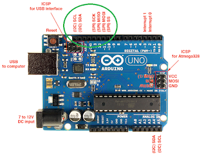
Step 2: Connecting HW. Below is a Arduino Uno pinout diagram (from http://www.electroschematics.com/7958/arduino-uno-pinout/). ArduCam OV2640 module has eight pins. Seven out of these eight pins are connected to the upper left corner of Uno board circled in green in the diagram.


As the figure below show, except for the pin of 5v, which is connected to the 5v pinout in lower end of the board, all other seven pins are connected to the upper left corner.


Step 3: SW setup. For code to be loaded to Uno board, we use an example program provided by ArduCam named ArduCAM_SPI_OV2640_FIFO_UART.ino. The link to this program from ArduCam's website is broken as on 2017/10/25. But the program can still be found in https://github.com/sumotoy/ArduCAM/tree/master/examples/REVC/ArduCAM_SPI_OV2640_FIFO_UART

ArduCAM_SPI_OV2640_FIFO_UART.ino enables camera configuration setup and image capture. In order to see the image from PC, we still need a host program. For host program in PC, we can use an ArduCam app named ArduCAM_host_v1.0.exe which can be downloaded from https://github.com/sumotoy/ArduCAM/tree/master/examples/mini

After opening this app from PC, you need to set COM port and Baud rate to match with what is used. Baud rate in default Arduino program is 115200. You need to find out COM port by yourself and Arduino GUI can be a good tool. The image resolution is set as 320x240, which already matches with the default. After setup done, press "Open" button. Then press "Capture" botton. If everything is set up correctly, you should see the image. Bingo!