Step 1: I already had a Arduino Uno board. Thus the first step is to find a camera module which can be connected to this board. After some googling, I found OV2640 module made by ArduCam. This module has a 2MP image sensor and can be conveniently connected to Uno board.
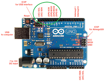
Step 2: Connecting HW. Below is a Arduino Uno pinout diagram (from http://www.electroschematics.com/7958/arduino-uno-pinout/). ArduCam OV2640 module has eight pins. Seven out of these eight pins are connected to the upper left corner of Uno board circled in green in the diagram.
As the figure below show, except for the pin of 5v, which is connected to the 5v pinout in lower end of the board, all other seven pins are connected to the upper left corner.
Step 3: SW setup. For code to be loaded to Uno board, we use an example program provided by ArduCam named ArduCAM_SPI_OV2640_FIFO_UART.ino. The link to this program from ArduCam's website is broken as on 2017/10/25. But the program can still be found in https://github.com/sumotoy/ArduCAM/tree/master/examples/REVC/ArduCAM_SPI_OV2640_FIFO_UART
ArduCAM_SPI_OV2640_FIFO_UART.ino enables camera configuration setup and image capture. In order to see the image from PC, we still need a host program. For host program in PC, we can use an ArduCam app named ArduCAM_host_v1.0.exe which can be downloaded from https://github.com/sumotoy/ArduCAM/tree/master/examples/mini
After opening this app from PC, you need to set COM port and Baud rate to match with what is used. Baud rate in default Arduino program is 115200. You need to find out COM port by yourself and Arduino GUI can be a good tool. The image resolution is set as 320x240, which already matches with the default. After setup done, press "Open" button. Then press "Capture" botton. If everything is set up correctly, you should see the image. Bingo!


No comments:
Post a Comment